Quantcast
Channel: Mobile Phone Repairing Archives - Mobile Phone Repairing
Viewing all 38 articles
Browse latest View live

Mobile Phone Parts Identification | How to Identify Parts & Components on PCB of Mobile Phone

$
0
0

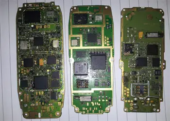
When learning how to repair a mobile cell phone, it is important to learn how to identify parts and components on the PCB of a mobile cell phone. Identification of these parts and components is not that difficult.

The PCB of any mobile phone of any brand namely Nokia, Samsung, Motorola, China Mobile Phones etc is divided into 2 Parts namely: (1) Network Section; and (2) Power Section. When identifying parts, electronic components and ICs on the PCB of a mobile cell phone, it is important to keep these two sections in mind.

How to Identify Parts and Components on the PCB of a Mobile Cell Phone:

  1. Antenna Point: The point where antenna is connected is called antenna point. It is normally located at the top of the PCB of a mobile phone.

Network Section: The section below antenna point and above power section is called network section.

  1. Antenna Switch: It is found in the network section. It is made from metal and non-metal. It has 16 points or legs. In some mobile phones, the antenna switch is merged with PFO.

    Antenna Switch of Mobile Phone

    Antenna Switch of Mobile Phone

  2. PFO: Power Frequency Oscillator. It is present beside the antenna switch.

    PFO of a Mobile Phone

    PFO of a Mobile Phone

  3. Network IC: It is below or beside the antenna switch and PFO. In some mobile phones, the Network IC is merged with the CPU. E.g.: Nokia 1200, 1650, 1208, 1209 etc.

    Network IC of a Mobile Phone

    Network IC of a Mobile Phone

Power Section: This section is below the Network Section.

  1. Power IC: In the Power Section, the IC around which there are several brown-colored capacitors is called Power IC. In some mobile phones there are 2 Power ICs.

    Power IC of a Mobile Phone

    Power IC of a Mobile Phone

  2. CPU: Central Processing Unit. In the power section, the largest IC is the CPU. In some sets there are 2 CPU.

    CPU of a Mobile Phone

    CPU of a Mobile Phone

  3. Flash IC: This IC is found beside the CPU.

    Flash IC of a Mobile Phone

    Flash IC of a Mobile Phone

  4. Logic IC: The IC with 20 legs is the Logic IC.

    Logic IC of a Mobile Phone

    Logic IC of a Mobile Phone

  5. Charging IC: In the Power Section, the IC beside R22 is the Charging IC.

    Charging IC of a Mobile Phone

    Charging IC of a Mobile Phone

  6. Audio IC: The IC parallel to Power IC is the Audio IC.

    Audio IC of a Mobile Phone

    Audio IC of a Mobile Phone

NOTES:

  1. UEM (Universal Energy Manager) = Logic IC + Charging IC + Audio IC + Power IC
  2. PFO (Power Frequency Oscillator) = Antenna Switch + PFO
  3. Flash IC= RAM + Flash IC

    Mobile Phone PCB Layout Diagram

    Mobile Phone PCB Layout Diagram

Related Posts:


How to Jumper in Mobile Phone Repairing

$
0
0

Most mobile phone repairing is done by doing jumper. Different parts of a mobile cell phone like display, keypad, speaker, microphone, LED lights, different ICs, different small parts and electronic components, all have different jumper settings. It is important to first track the fault or missing track and then do the jumper.

Mobile Phone Repairing Tools You Will Need to Dumper

  1. Mobile phone jumper wire.
  2. Soldering iron.
  3. Solder wire.
  4. Blade cutter.
  5. Multimeter.
  6. Soldering flux.
  7. PCB holder.
  8. Tweezers.

How to Jumper

  1. Disassemble mobile phone and place it on a PCB holder.
  2. Using a multimeter, check track and find the fault or the missing track that need jumper.
  3. Apply liquid soldering flux to the points where you need to solder jumper wire.
  4. Cut jumper wire to desired length and remove its lamination using blade cutter.
  5. Hold one end of the jumper wire and solder it to one point of the faulty circuit track. Use a good quality tweezers to hold the wire and good quality of soldering iron and solder wire to solder.
  6. Now hold the other end of the jumper wire and solder to the other point of the track
  7. Using a multimeter check the jumper.

Related Posts:

How to Clean Points and Connectors of Mobile Phone PCB

$
0
0

When doing mobile cell phone repairing, you will often have to clean several points and connectors. Cleaning of points and connectors is done to clean and remove dirt and oxides from solder joints, PCB circuit tracks and the PCB itself. These dirt and oxides (often copper oxide and carbon oxide) act as resistance and hindrance to flow of current thus affecting the performance of the mobile phone handset.

Tools Needed to Clean Mobile Phone Points and Connectors:

How to Clean Points and Connectors of Mobile Phone PCB (Printed Circuit Board)

Mobile Phone PCB

Mobile Phone PCB

  1. Disassemble the mobile phone and take out the PCB
  2. Fix the PCB to a PCB holder that can hold it firmly.
  3. Using a PCB cleaning bud or ESD-Safe Brush and IPA solution or PCB cleaner, clean the points and connectors on the PCB.
  4. You can also use tweezers to clean the points and connectors.
  5. Similarly you can clean the whole PCB of the mobile phone and other parts and components in a mobile phone.

Have a look at following videos to learn and understand how to disassemble a mobile cell phone and how to clean points and connector of a mobile phone PCB.


Related Posts:

How to Check Parts of a Mobile Phone for Fault

$
0
0

When doing mobile phone repairing, you will often need to check parts such as speaker, ringer, vibrator, coil, boost coin, On / Off Switch, Antenna Switch, RX Filter, PFO, BSI, Network IC, VCO, Audio IC, Power IC, RTC, Charging IC, CPU, R22, Microphone Interface, Bluetooth IC, Flash IC, RAM, Logic IC, UEM etc.

In most cases, only card level parts of a mobile cell phone are checked for fault and then repaired or replaced with a new one. Card level parts of a mobile cell phone include ringer, speaker, microphone, vibrator, LED, charging connector, headphone connector, data cable connector, battery, battery connector, SIM card, SIM card connector, memory card, memory card connector, camera, camera connector, keypad button, keypad connector, ON / OFF Switch, Display, Display connector, Internal antenna and PDA.

Chip level small parts of a mobile phone that include small electronics components like capacitors, resistor, diode, coil, boost coil, coupler, regulator, transistors, are rarely or not tested for fault. In case there is any fault in the track of the Mobile Phone PCB then it is solved or fixed by jumper.

Mobile Phone Tools and Equipment Needed to Check Parts of a Mobile Phone for Fault are:

How to Check Parts of a Mobile Phone for Fault

  1. Ringer: To check if the ringer of a mobile phone is faulty or damaged,
    Multimeter for Mobile Phone Repairing

    Multimeter for Mobile Phone Repairing

    keep the multimeter in buzzer mode and check the ringer. Value must be between 8 to 10 Ohms. If the value is between this range then the ringer is good and does not need replacement. If the value on multimeter is 4-5 or 12-14 then change the ringer.

  2. Vibrator or Motor: Keep the multimeter in Buzzer Mode and check the vibrator, Value must be 8 to 16 Ohms. If the value is between 8-16 Ohms then the vibrator is good. Otherwise change it.
  3. Speaker or Earpiece: Check the speaker / earpiece with a multimeter on Buzzer mode. Value must be in the range of 25 to 35 Ohms. If the value is in this range then the speaker / earpiece is OK and need not be changed. Otherwise, change the speaker / earpiece.
  4. Microphone or Mic: Keep the multimeter in buzzer mode and check the microphone. Value reading on the multimeter must be in the range of 600 to 1800 Ohms. There will also be a Beep or Buzz sound from the multimeter. NOTE:  Please note that only one side of the microphone will show value. If we check by reversing the Red and Black Probes / Test Leads of the multimeter and check the microphone then there will be no value.
  5. Coil: Check it with a multimeter on Buzzer Mode. If it is good then it the multimeter will give a Beep or Buzz sound. If there is no sound then the coil is faulty. Replace it with a new one.
  6. Resistor or Resistance: Check it with a multimeter on Buzzer Mode. If it is good then the multimeter will give a Beep or Buzz sound. If there is no sound then the resistor is faulty. Replace it with a new one.
  7. Capacitor: Check it with a multimeter on Buzzer Mode. If it is good then the multimeter will NOT give any Beep or Buzz sound. If there is sound then the capacitor is faulty. Replace it with a new one.
  8. Diode: Check it with a multimeter on Buzzer Mode. If it is good then the multimeter will NOT give any Beep or Buzz sound. If there is sound then the diode is faulty. Replace it with a new one.
  9. LED: Keep the multimeter in Buzzer mode and check the LED. If the LED is good then they will glow otherwise not.
  10. Coil and Boosting Coil: Check for continuity. If there is continuity then the coil or the Boost Coil is good otherwise it is faulty.
  11. Keypad: Keep the multimeter on Buzzer mode and check Rows and Columns or the Key Pad. If there is Beep or Buzz sound from the multimeter then Keypad is ok, otherwise it is faulty.
  12. Battery Connector: Keep multimeter on 20V DC and check. Value must be 1.5 to 3.5 V DC.
  13. Battery: Check voltage with a multimeter. Keep multimeter on 20V DC and check. Value must be 3.7 V DC or above.
  14. ON / OFF Switch: Check voltage with a multimeter. Keep multimeter on 20V DC and check. Value must be between 2.5 to 3.7 V DC.
  15. Network IC: Use a Analog DC Power Supply to check Network IC. Switch ON DC Power Supply and call any number from your mobile phone. The Needle of the DC Ampere will start moving. This shows that the Network IC is OK and not fault.
  16. Power IC and CPU: Adjust voltage of the DC Power Supply to 4.2. Place the Red Probe / Test Lead of the DC Power Power Supply to the “+” of the Battery Connector of the mobile phone and the Black Probe / Test Lead to “-“. If DC Ampere is over 6 then Power IC or CPU is damaged. Check by replacing Power IC and the CPU one by one.
  17. If there is no movement of the Ampere Needle of the Power Supply then the Battery connector, On / OFF Switch Track, RTC or Network Crystal is damaged. Give heat to these components using hot air blower. If the problem is not solved then check by replacing them one by one.
  18. If the Ampere Needle fluctuates below 2 ten there could be problem with software or RTC (Real Time Clock).
  19. If the Ampere needle stands at some fixed point then there is problem with the Flash IC.
  20. If there is beep sound from the DC Power Supply then there is problem with “+” and “-” or the mobile handset is short.

PS: When checking a faulty mobile phone with DC Power supply, connect the Red Probe to “+” and Black Probe to “-” of the Battery Connector of the Mobile Phone.

DC Power Supply

DC Power Supply

Notes:

  • Most mobile phone repair people and technician check only above parts of any mobile phone to solve hardware problems.
  • All other parts including electronic components and ICs are generally not checked for fault. There is no good sure test for these parts. The problem is either solved by jumper or by trial and error (check by replacement).

Related Posts:

Mobile Cell Phone Screen Touch (PDA) Not Working Problem and Solution – How to Solve Screen Touch (PDA) Fault in any Mobile Cell Phone

$
0
0

This chapter explains Mobile Phone Screen Touch (PDA) Problem and Solution – Mobile Phone Screen Touch (PDA) not working and How to Solve Screen Touch (PDA) Fault in any Mobile Cell Phone. These problem and solution apply to all brands and make of mobile phones including Nokia, Samsung, iPhone, China Mobile Phones, Motorola, HTC, Sony, Blackberry, Alcatel, Apple, AudioVox, Benefone, Danger, FIC, Hagenuk, Palm, Kyocera, LG, Panasonic, Huawei, ZTE, Spice, Lava, Sony Ericsson, Micromax etc.

What is Screen Touch (PDA) in a Mobile Cell Phone?

Screen Touch (PDA)in a mobile cell phone is an electronic component or part that helps to operate a mobile phone by touching the screen. Touch Screen is available in different sizes. It normally has 4 Points namely: – (+), (-), (RX), (TX). Screen Touch is also called PDA. It is controlled by the CPU. In some Mobile Phones there is an Interface IC called PDA IC or Screen Touch IC.

Types of Faults or Problems with Screen Touch (PDA) in any Mobile Cell Phone

  • Screen Touch not working.
  • Only Half Screen Touch Works.
  • One key is pressed and some other key works.

Mobile Cell Phone Screen Touch (PDA) Not Working Problem and Solution – How to Solve Screen Touch (PDA) Fault in any Mobile Cell Phone

  1. Check Settings if the Mobile Phone has Both Keypad and Touch Screen.
  2. Clean and Resold PDA Tips and PDA Connector.
  3. Change PDA.
  4. Check Track of the PDA Section and Jumper if Required.
  5. PDA IC: Heat or Change.
  6. CPU: Heat, Reball or Change.

Note:

  • If the PDA Problem is not solved by Hardware Then Reload Software to Solve the Problem.
  • Construction of PDA

    Construction of a Mobile Phone PDA

    Construction of a Mobile Phone PDA

  • Any PDA of SAME Size will Fit any Mobile Phone.  Any One of the Following 5 Jumper Settings will Work:

    Mobile Phone PDA Screen Jumper Solution

    Mobile Phone PDA Screen Jumper Solution

Related Posts:

Sections and Parts Inside a Mobile Cell Phone

$
0
0

Any mobile cell phone including – Samsung, Nokia, LG, Motorola, Sony Ericsson, Acer, Alcatel, Apple, Amoi, Asus, BenQ, Siemens, Bird, Blackberry, Blu, Celkon, Dell, Gigabyte, Haier, HTC, Huawai, Micromax, Panasonic, Philips, Sagem, Spice, Toshiba, ZTE Etc have different parts or sections inside the mobile cell phone. These parts can be divided into following different sections:

Parts Inside a Mobile Cell Phone

Parts Inside a Mobile Cell Phone

  1. Keyboard or Keypad Section: The keyboard section of any mobile cell phone is directly connected with the CPU. This means that rows and columns of keys are directly connected with the CPU. Protector IC or Interface IC or Verector diode is connected in the row or column line for the protection of key section. In modern mobile cell phones which have qwerty keys, a separate control IC is connected with the CPU for extra protection to the keys.
  2. Display Section: The display section is directly connected with the CPU to receive following signals – LCD Data Signal, LCD Reset Signal, LCD WR Signal, LCD RD Signal, LCD FLM Signal, LCD HSYN Signal etc. These signals are given to the LCD Module through the CPU. 2.8V power supply or 1.8V power supply is given to the LCD for functioning. LCD signal interface filter are connected in many mobile cell phones for interfacing these signals of LCD Module.
  3. SIM Card Section: The SIM Card Interface section is directly connected with the CPU in most mobile cell phones. If there is no power supply in a mobile phone then the SIM section is connected with the CPU through the Power IC. Mainly V-SIM (3.0V), SIM-RST (2.85V), SIM CLK, SIM-Data (2.5V), and SIM GND are made in the SIM Section. These four pins (Beside (SIM GND) are directly connected with the SIM interface / control section and V-SIM volt are given to the SIM data pin from V-SIM pin through the 10-18 Kilo Ohms Resistance.
  4. Memory Card Section: Now mostly Micro SC Card is connected in most mobile cell phones which is connected with micro card section through a 8 pin socket. Memory card section is made inside the CPU. Description of these 8 pins are as follows:
    1. MMC-Data-2
    2. MMC Data
    3. MMC CMD (Command)
    4. VMMC / VSD (Positive Supply Pin)
    5. MMC-CLK
    6. GND
    7. MMC-Dta0
    8. MMC Data-1

    2.8 Volt Power is supplied to Pin Number 4 from Power Supply for functioning of the MMC Card and connection the 50 tp 100 Kilo Ohms resistance in this power supply. This power supply is given to Pin Numbers – 1,2,3,7,8 of MMC Socket. One MMC detector switch or pin is made in MMC socket at which, if there is no MMC Card then 1.8 V power is continuously received and after the MMC is connected, it becomes zero.

  5. MIC Interface Section: MIC interface section is directly connected with the CPU inmost mobile phones. Working voltage (MIC Bios) (1.8 to 2.8 V) is supplied from the CPU or the Power Supply Section for functioning of the MIC and MIC Positive and Negative Volt are input through two capacitors.
  6. Ear Speaker Section: In most modern mobile cell phones, in which there is a separate ear speaker, it is directly to the CPU. It receives sound via signals directly from the CPU of from the audio section inbuilt within the CPU. In some mobile phones, these sound signals are received via coil / resistance. Some mobile phones have audio IC in the audio section. Some mobile phones have audio amplifier.
  7. Speaker / Ringer Section: Ringer, Buzzer or Speaker in most mobile phones are connected with the audio amplifier IC to obtain loud sound. The amplifier IC amplifies the sound or audio signal received from the CPU of the audio section.
  8. Key Backlight Section: LED Lights are connected according to the parallel circuit in the key backlight section. Anode ends of all the LEDS are connected to each other and all the cathode ends are to each other. 3 to 3.3 V is supplied for the functioning of these Key LED Lights. This power supply is given to the cathode ends of LEDs from the ground ends. Power supply to the anode ends of LED Lights is controlled bu using LED-Driver or PNR IC.
  9. LCD Backlight Section: LCD Backlight in mobile cell phones is made according to the series circuit. A Boost Voltage Generator Section is built for the supply of high voltage (10 to 18V) for the functioning of the LCD LED. Boost coil, Boost Volt Driver IC, Rectifier Diode etc are present in this section.
  10. Vibrator Motor Section: Positive power supply is given to this section directly from the positive end of the battery. Negative power supply is given through a NPN transistor or from the ground of any circuit.
  11. Network Section: Antenna, External Antenna Socket, RX-Band Pass Filter, RF Crystal, FEM, PFO, TX-Band Pass Filter, RF IC, CPU are connected in the Network Section. Signal received at the antenna during the RX is given to the antenna switch or FEM through the antenna socket where the next processing is completed by selecting a frequency of proper band and is passed on to the RF IC through RX-Band Pass Filter. RF Signal out from the RF IC during TX is given to the FEM or PFO to amplify the signal. After the Band Selection Process the signal is passed through the antenna.
  12. Battery Charging Section: Charger and system interface connector is made together in most modern mobile cell phones. Regulator section is made separately for the battery charging section. In some mobile phones, the battery charging section is made inside the Power IC.
  13. FM Radio Section: FM Radio Driver IC, FM Antenna, Signal and Supply Components are made in the FM Radio Section.
  14. Bluetooth Section: Bluetooth Antenna, Bluetooth RF Signal Filter, Bluetooth Driver IC, Supply and Signal Components are made in this section. The Bluetooth sections functions like the Network Section. RF-CLK signal is given to the Bluetooth driver IC during signal processing.
  15. Set Power ON: Power IC, CPU (UCP), Flash IC, RF-CLK, Crystal, RF-IF, PWR Ket etc components are present this section. Battery positive supply is given to the power IC and connecting the battery (3.7V) from 2.87 to 3.0 Power ON Volts are received at one tip of the Power Key. Supply is given to the CPU, Flash IC, RF-CLK, Generator Section (RF Crystal, RF IC) by which the mobile phone gets switched ON.
  16. Handsfree (Earphone Section): Mainly hands free jack, hands free MIC, speaker signal component and hands free audio amplifier are present in this section. Hands free symbol is displayed after connection the Handsfree jack.
  1. Smartphone Repairing

Mobile Phone Repairing Testing Methods

$
0
0

Faults in each part, component or section of a mobile cell phone can be repaired fast by using following 2 methods at the time of repairing mobile cell phone. These methods can also be used to find out faulty or damaged parts or components inside a mobile cell phone.

  1. Cold Testing Method: When we check the value of resistance using a multimeter at the time of repairing a fault in any mobile phone, it is called cold testing. There is no need to give any power supply to the faulty mobile phone from any equipment such as DC Power Supply or battery during cold testing. Diode Range and Beep Sound from the multimeter is used to find fault in a mobile cell phone using the cold testing method of mobile phone repairing. In this testing method, the RED Probe of the multimeter is connected to the ground of the mobile phone PCB and the BLACK Probe is touched at the testing points of the mobile phone. During the fault finding and repairing process of each part, component or section, following correct values will be received:
    1. Ear Phone Connector Tip (+ , -): .500 to .700
    2. Loud Speaker / Ringer Connector Tip (+,-): .300 to .600
    3. Battery Connector Tip (+): .400 to .500
    4. Battery Connector Tip (Sense): above .800
    5. Display Connector Supply Pins: .250 to .400
    6. Display Connector Signal Pins: .500 to .800
    7. Camera Connector Supply Pins: .250 to .400
    8. Camera Connector Signal Pins: .600 to .900
    9. Key Tip (Row and Column): .400 to .800
    10. Charger Connector Tip: .600 to .700
    11. Vibrator Motor Connector: .40 to .500
    12. Power ON / OFF Switch Point (+): .600 to .900
    13. MIC Connector Tip (Analog MIC) (+,-): .700 to .900
    14. Battery Charging Out Point (+,-): .300 to .400
    15. SIM Card Connector Pin 1 (VSim): .500 to .700
    16. SIM Card Connector Pin 2,3,6: .400 to .800
    17. SIM Card Connector Pin 4 (GND): .00 (Beep)
    18. Micro SD Card Connector Pin 4: .500 to .600
    19. Micro Card Connector Pin 6 (GND): .00 (Beep)
    20. Micro Card Connector Pin 1,2,3,5,7,8: .600 to .800
    21. RTC: .400 to .500
    22. Data RX and TX Pins: .600 to .700
  1. Hot Testing: This is the second method of fault finding and repairing any mobile cell phone. Hot testing method of mobile phone repairing is adopted when the fault cannot be found or when the phone cannot be repaired using the Cold Testing Method. In this method, VOLTAGE of damaged part, component or section of a mobile phone is checked. The fault is found by giving Power Supply to the mobile phone with a Battery of DC Power Supply Equipment such as DC Power Supply. In this method, DCV (DC Volt) range of the Multimeter is selected. The BLACK Probe of the multimeter is connected with the Ground of the Mobile Phone PCB and the RED Probe is touched at the Testing Points. During Hot Testing method, Voltage of different part or sections should be as follows (All Values in Volt):
    1. Ear Phone Connector Tip (+ , -) during working: .0 to 2.5
    2. Loud Speaker / Ringer Connector Tip (+,-) during working: .0 to 2.5
    3. Battery Connector Tip (+): 3.7
    4. Display Connector Supply Pins: 1.8 to 2.9
    5. Display Connector Signal Pins During Working: .0 to 1.8
    6. Camera Connector Supply Pins: 1.8 to 2.9
    7. Camera Connector Signal Pins During Working: .0 to 1.8
    8. Key Tip (Row and Column) One Side: 1.8 to 2.8
    9. Charger Connector Tip: 5 to 6
    10. Vibrator Motor Connector Tip During Working: 1.9 to 3.6
    11. Power ON / OFF Switch Point (+): 3 to 3.6
    12. MIC Connector Tip (Analog MIC) (+,-): 1.8 to 3.0
    13. Battery Charging Out Point (+,-): 3.7 to 4.2
    14. SIM Card Connector Pin 1 (VSim) When SIM Connected: 1.8 to 3.0
    15. SIM Card Connector Pin 2,3,6 During Working: 0 to 2.8
    16. Micro SD Card Connector Pin: 2.8
    17. Micro Card Connector Pin 1,2,3,5,7,8: 0 to 2.8
    18. Data RX and TX Pins: 1.8 to 2.8
Mobile Phone Repairing

Mobile Phone Repairing


Related Posts:

Mobile Phone Fault Finding for Mobile Cell Phone Repairing

$
0
0

In order to repair any mobile cell phone through circuit, we must know the section in which the fault is present and different parts and components present in that particular section. If we know different parts and components present in different sections inside a mobile cell phone then we can easily repair the fault by checking the component.

While doing mobile phone repairing, we can do fault finding if we know different sections inside a mobile cell phone. For Example – If there is Network Problem in a mobile phone then we can easily repair the phone if we know different parts, components and their function in the Network Section.

Mobile Phone Repairing

Mobile Phone Repairing

Following are different electronic parts and components in different sections inside a mobile cell phone:

  1. Network Fault: Antenna Switch, PFO, FEM, RF IC, VCO, RX-Filter, TX-Filter, RF Antenna, RF Crystal, External Antenna Socket, Network Signal and Supply Control and Interface Section. If we know about the parts and components present in the Network section and their function then we can easily repair the fault by looking at the code number of the faulty component in the Circuit Diagram and the PCB Layout Diagram. In this way we can easily make good use of circuit diagram for mobile cell phone repairing.
  2. Power ON Fault: Battery (3.7V), Battery Connector Jack, Power IC, CPU, Flash IC, S-RAM IC, RF Crystal, RF Clock Section Component, RF IC, Power ON / OFF Trigger Components.
  3. Charging Fault: Charger (5-6V), Battery (3.7V), Charger Connector, Charger Volt Fuse, Coil, Charger Over Volt Protector, Charging IC, Power IC, Charging Regulator, Charging Volt Output Components, Charger and Charger Volt Detector Components.
  4. SIM Fault: SIM Card, SIM Socket, SIM Signal and Supply Interface Components, Resistance, Coil, Power IC, CPU etc.
  5. Ringer Fault: Ringer, Ringer Signal Input and Output Components, Audio Amplifier IC, Power IC, CPU etc.
  6. Ear Speaker Fault: Ear Speaker, Ear Speaker Signal Components, Audio Amplifier IC, CPU, Power IC etc.
  7. Micro SD Card Fault / MMC Fault: Micro SD Card, Micro Card Connector, Micro Card Detector Switch, Micro Card Detector Signal Components, CPU etc.
  8. USB and Bottom Connector fault: USB and Bottom Connector, USB and Signal Interface Connector Components, USB Signal Interface IC, USB Driver IC, CPU etc.
  9. Keypad Fault: Key Tip, Key Pad Dot Sheet, Key Signal Filters, Key Signal Varactors, Key Board to Key Connector, CPU etc.
  10. Display Fault: LCD, LCD Connector, LCD Supply Components, LCD Signal Interface Filter IC, CPU, LCD Signal Interface Resistance etc.
  11. MIC Sound Fault: MIC, MIC Interface Connection, MIC Signal and Supply Components, Power IC, CPU etc.
  12. Backlight (LED) Fault: LED, Backlight Driver IC, Backlight Driver Section Components, Power IC, CPU etc.
  13. Bluetooth Fault: Bluetooth Antenna, Bluetooth Driver IC, Bluetooth Section Crystal, CPU etc.
  14. FM Radio Fault: Fands Free Lead, Hands Free Connector, FM and Bluetooth IC, FM Driver IC, CPU etc.
  15. Vibrator Fault: Vibrator Motor, Vibration Supply Components, Power IC, Vibrator Driver IC etc.
  16. Touch Panel (PDA) Fault: Touch Panel / PDA Panel, Touch Panel Control IC, CPU, Signal Interface Parts etc.

Related Posts:


Smartphone Repairing – Android and iPhone

iOS / iOS 7 Not Responding – Problem and Solution

How to Reset iPhone (All Models) – Soft Reset / Hard Reset / Factory Reset

iPhone Touchscreen Not Working – Problem and Solution

Samsung Galaxy S5 Problem and Solution

HTC One M8 Problem and Solution

Sony Xperia Z2 Problem and Solution


How to Diagnose Mobile Phone Problem – Diagnostic Codes

How to Increase Battery Life of Smartphone

Mobile Phone Repairing Tutorial, Tips, Free PDF Download

How To Repair and Fix Wet Water Damaged Mobile Phone

DIY Mobile Phone Repairing Guide

Viewing all 38 articles
Browse latest View live